Additional solar oven designs for heating soil, potting media, and nursery containers
Version 2/16/2025
Introduction
Solar energy can be used to heat soil, potting media, and contaminated hardware (nursery containers, tools, planting hardware, etc.) to temperatures to kill plant pathogens (including fungi, Oomycetes (e.g., Phytophthora species), bacteria, and viruses), as well as insects and weed seeds. These organisms can be killed by exposure to temperatures between about 50 and 100 C (120-212 F) for at least 30 minutes. These temperatures can be achieved with direct solar heating in several ways, including solar ovens, non-vented greenhouses (essentially large solar ovens), or tarping with clear (not black) plastic. Solar ovens are smaller and cheaper to construct than greenhouses and and are much more efficient for heating materials compared to solarization using clear plastic films.
Solar ovens used for sanitizing materials using heat can be designed and constructed in a variety of ways. This allows customization for specific use situations and constraints. Construction methods and performance data for a portable solar oven designed for field use are presented on another page at this website. Here we describe other solar ovens designed for heat-treating materials to eliminate plant pathogens and other plant pests. More general discussions of heat treatment principles and options are available elsewhere on the Phytosphere website and at the UC Davis AIR Nursery Program website.
Solar oven basics
Heating in a solar oven of the type described here works in the same way as in a greenhouse. Solar radiation (sunlight) enters the greenhouse through a clear boundary layer (glass or plastic). Glass and thermal plastic films used for greenhouses allow visible light and short-wavelength infrared (IR) light to pass through, but have low transmissivity to long-wavelength IR light. Solar energy that is absorbed by materials in the greenhouse and converted to heat are reradiated as long-wavelength IR light that does not readily escape through the glass or plastic, which increases the temperature of materials in the greenhouse. In a solar oven, the clear boundary layer is limited to an area that is facing the sun. All other surfaces (walls and floor) are insulated and coated with a heat resistant reflective material to minimize heating of these surfaces and maximize reflection long-wavelength IR toward materials that are being heated. Absorption of IR energy is more efficient if the objects to be heated do not reflect incoming light energy, so dark or black objects will heat more efficiently than light colored or reflective items.
Solar heating is greatest when the sun is most intense, in midsummer, and when the solar angle above the local horizon (solar altitude) is greatest ("peak hours", 2 to 3 hours on either side of solar noon), and when skies are clear and free of clouds, haze, or smoke. Solar ovens will heat most efficiently if the entire interior of the oven is unshaded and aligned directly at the sun. Heating can be maximized if you are able to rotate your solar oven to maintain this situation as the sun's position moves across the sky. Alternatively, a non-movable oven can be oriented so that it will receive maximum solar energy at peak hours. External reflectors can also be used to direct solar energy from a wider area into the oven and minimize internal shading in the oven during the day.
Solar oven materials
Because air temperatures in solar oven can exceed 100 C (212 F) and dark absorptive surfaces may reach even higher surface temperatures, materials in the oven interior must be able to withstand these temperatures. Weight considerations of materials come into play for the oven opening and if the oven is to be moveable. Outer surfaces of the oven must be tolerant of full sun exposure.
Clear boundary layer
- Glass: standard window glass is weather resistant and withstands solar oven temperatures but subject to breakage on impact. Tempered glass is more resistant to breakage. Glass should not have thermal coatings that inhibit short wavelength IR transmission. Framed glass panes from window replacement projects may be available at low or no cost.
- Rigid plastics: clear plastic panel materials vary in their ability to tolerate solar oven temperatures. Acrylic sheet ('plexiglass') will deform at temperatures reached in hot solar oven. Polycarbonate panels have higher heat tolerance, but check specifications or test a sample before use.
- Plastic sheeting: 6-mil thermal greenhouse films are the best choice for this use but have a limited life (1-4 years, depending on material). Select materials that are rated for have high levels of light transmission and reduced heat loss (IR) but do not have reduced daytime heat gain. Large surfaces covered with these flexible films will need a supporting structure. The film will sag when it gets hot.
Insulation
- Polyiso foam insulation panels: rigid foam panels made of polyisocyanurate foam are light weight and easily cut to the desired size and shape. We have found them to be superior to polystyrene foam panels, which we used previously. Polyiso panels 2 inches (5.1 cm) thick have a reasonable amount of structural stability, minimizing the need for other structural layers or supports. However, the panels need to be covered (see below) to provide durability.
Cladding
- Aluminum flashing: This is the preferred cladding for insulation panels on the interior surfaces of the oven because it is reflective and protects the panel surface. It can also be used the clad the outside of the panels. It is reasonably easy to cut and shape, but be aware of sharp edges.
- Weather-resistant plastic panels: Instead of aluminum flashing, opaque UV-stabilized plastic sheet materials can be used to cover the outside surface of the foam panels, if a compatible adhesive (see below) used to attach them.
- Edge flashing: The narrow edges of the foam panels need to have a straight, smooth covering where gaskets are needed to seal the oven. Thin aluminum or steel U- or J-channel is ideal for this use but is not easily available at the necessary 2 inch (5.1 cm) channel width. L-angle material (e.g., roof drip edge flashing) is a cheaper and more easily obtainable material that can be used.
- Construction adhesive: This is used to bind the interior and exterior cladding on the foam insulation panels. Look for materials rated for outdoor use, heat resistance (especially for the interior oven surfaces) and the type of cladding you plan to use.
- Fasteners: Pop rivets and short sheet metal screws are useful for holding metal cladding layers in place at joints. Screws should be long enough to extend some distance into the foamboard to help hold the cladding layers in place.
- Aluminum foil tape: Good quality aluminum foil tape (commonly used for HVAC ducting) is useful for helping to seal metal flashing seams and cover rough edges inside of the oven.
Platform
- Stationary ovens: Ovens that are intended to be stationary can be attached to a convenient base (table, nursery bench, etc.) that will support the weight of the oven plus its contents. The flat surface should support the foam panel at the bottom of the oven if that will bear the weight of the contents. An alternate oven design uses legs attached to a weight-bearing wire shelf above the bottom foam insulation board. For that design, the legs that support the shelf can extend to the ground or another stable surface.
- Mobile ovens: Depending on the size of the oven, a moveable platform can be based on a steel nursery, utility, or other cart. Alternatively, wheels or casters can be mounted on another flat surface that supports the foam panel at the bottom of the oven (or the supporting legs if the alternate oven design is used).
A moveable back-loading solar oven
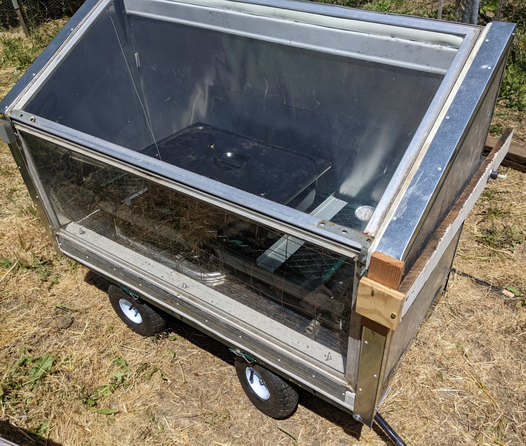 Figure 1. This solar oven features a glass top and front (aluminum-framed ~4 x 2 ft and ~4 x 1.5 ft sliders, respectively), polyiso foam insulation (2 inches=5.1 cm thick) walls and floor, aluminum flashing cladding on interior walls, a combination of reused aluminum flashing and galvanized steel sheet metal on exterior walls, and a removable rear wall. The platform is a modified garden cart.
Construction details
If you use a framed glass window, sizing of other components will depend on the window dimensions. For the oven in Figure 1, the top window is a framed nominal 4 x 2 ft slider. Because the window is mounted on angles attached to the inside of the side walls, the minimum platform (utility cart bed) length is 4 ft 4 inches (for 2 inch-thick sidewalls). The front wall (in this case, another framed slider window, nominal 4 x 1.5 ft) needs to match the width of the top window. An alternative arrangement for mounting the top window is to rest the edges on top of the side walls (Figure 2), in which case the platform and window lengths will be the same.
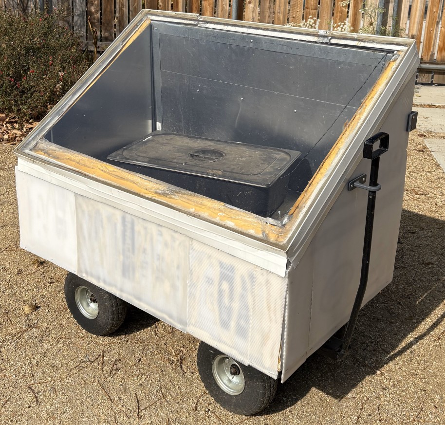 Figure 2. This solar oven features a glass top (unframed 4 x 3 ft window pane), polyiso foam insulation (2 inches=5.1 cm thick) walls and floor, aluminum flashing cladding on interior walls, plastic sheeting on exterior walls, and a removable rear wall. The platform is plywood to which garden cart wheel assemblies were attached. Note that the window is mounted on the top edges of the side walls.
The width of the platform is somewhat more flexible because the window can be inclined at a range of angles as long as shading within the oven is minimized. In the case of the oven in Figure 1, the minimum width was set to accommodate the steam table pans that are used for holding soil or media. The platform width was extended slightly to provide sufficient interior width for the pans, plus space for air circulation around them on all sides.
Note that if you use plastic sheeting (greenhouse film) instead of glass, it is easier to design the oven box based on desired interior dimensions and cut the film to size. Rigid plastic sheets can also be cut to size but maximum sheet dimensions may constrain the size of the oven box.
Our other solar oven design, was made to be transported to a remote location in a flat, dismantled state, so all edges of the wall and floor panels were covered with sheet metal J channel. Construction is somewhat simplified for the cart-mounted solar oven shown here that is not intended to be dissembled, with the exception of the removable rear wall. Once the basic fixed dimensions are determined, the general order of construction is as listed below. Be sure to check the overall fit as you go along to account for dimensions after the cladding is applied. Also, dimensions may shift a bit as parts are attached together. Use heat-resistant weather stripping or flexible caulk (e.g., silicone) at all joints. The finished oven won't be entirely airtight, but it should be close to that for good heating efficiency.
- Prepare the platform: make any modifications needed to the platform to provide a flat, stable base for the floor and walls of the oven. Make sure that the removable back wall will have adequate support. For the oven in Figure 1, a plywood based was mounted on the utility cart to provide a flat surface.
- Floor insulation panel: Cut this to size and place on the platform. It will be secured later.
- Wall insulation panels: Cut these to size. Check that the walls will fit tightly together and will sit flat on the floor panel. You will need some clamps and possibly some temporary supports to hold the pieces together to check for fit. Mark the bottom panel along the inside edges of the wall panels.
- Cut interior aluminum flashing: It will be easier to measure, bend, fit, and glue the aluminum flashing pieces on the walls and floor before attaching the wall panels to the floor. If multiple pieces of flashing are needed to cover the walls or floor, allow for at least 2 inches (5 cm) of overlap at the seam. For walls, overlap higher pieces over lower ones (shingle style). Use aluminum tape to secure the edge of the flashing that will be overlapped to the insulation board.
- Starting with the floor, cut the aluminum flashing large enough to allow at least 3 cm (1.25 inch) extra at each corner where these pieces meet the wall panels. After cutting slits at the corners, bend this extra length upward at a right angle as shown in Figure 3. The flashing on the wall panels will overlap these tabs, providing a clean, solid corner. For the side with the removable wall (and the front wall if a window is used), L angle drip edge flashing will be used to cover the edge, so the aluminum flashing should not extend beyond the edge of the panel. Note: The tool used to make sharp bends in sheet metal or flashing is known as a brake. A quick online search will turn up various videos showing how to make clean bends without a brake. Fortunately, aluminum flashing bends very easily.
- Interior wall flashing is prepared similarly. Allow 3 cm (1.25 inch) excess along the top and vertical edges. The extra length will be bent to partially cover the edge of the panel (Figure 4). These edges will later be covered with L drip edge flashing, so the aluminum flashing tab does not need to cover the whole edge. If you are using U or J channel over the edges instead if L flashing, you do not need to leave the extra length to fold the flashing over the edges. Cut the bottom edge, which will rest on the floor, with no overlap beyond the panel edge.
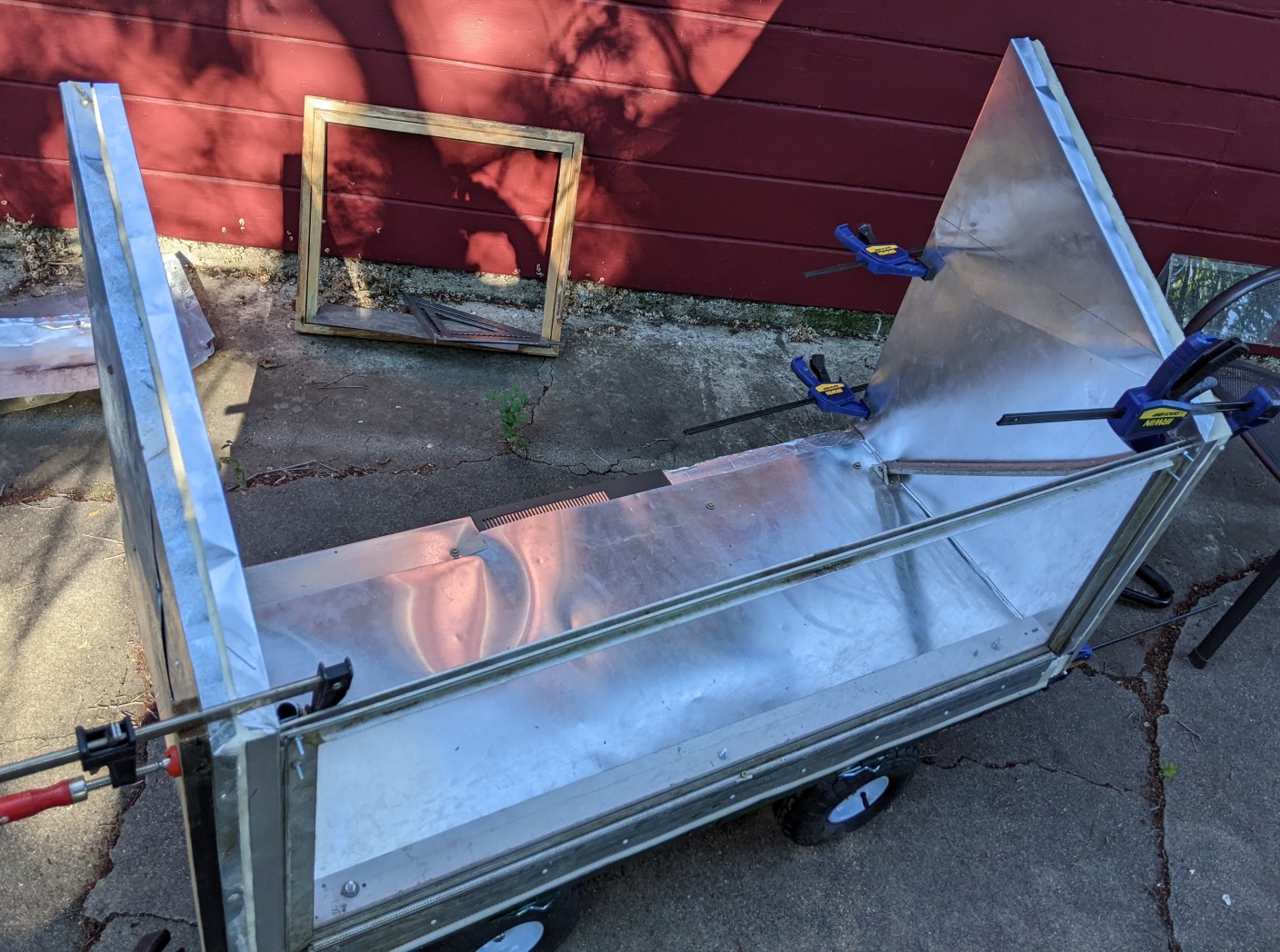 Figure 4. Partially constructed oven. Note flashing (both interior and exterior on left wall, only interior on right wall) are bent to partially cover the wall edges. Also wall flashing covers the upward bent edge from the floor flashing. Angled tubing connected to front window frame supports it, white metal channel (inside) and metal trim (outside) seal the window bottom and keep it in place.
 - At this point, you can also cut aluminum flashing for the outside surfaces of the wall panels. The only side that should be cut long is the bottom, which should extend over the edge of the bottom panel. Since that edge is 2 inches wide, cut the bottom edge of the outside 2 inches longer than the bottom of the wall. This also applies to the front wall if you are using a panel instead of a window.
- Glue flashing on the panels. After testing the fit and placement with the walls held in place, glue the flashing onto the bottom panel using construction adhesive. Avoid getting adhesive on the non-glued side of the flashing. Use a roller over the aluminum to flatten the adhesive layer and place boards with weights over the flashing until the adhesive is set.
- After checking the fit, use construction adhesive to glue the flashing onto the inside faces of the walls. Do not apply adhesive on the bottom 1.5 inches of the walls because this part will slip over the aluminum tabs from the bottom panel (Figure 4). You can also glue on the outside flashing, but be sure that the interior flashing doesn't shift if the adhesive is not set. You can then sandwich the clad walls between boards and clamp them together until the adhesive sets. Alternatively, place the wall panel on a flat surface, and cover it with a weighted board until the adhesive sets.
- Attach the oven floor to the platform. Use either multipurpose screws long enough to extend through the floor panel and screw into the platform (e.g., if plywood is beneath the panel) or use machine screws long enough to bolt though the panel and the underlying platform. After drilling necessary holes, insert each screw through a 1 inch (2.54 cm ) diameter fender washer on the top of the aluminum-clad panel. The fender washer will keep the screw head from tearing through the aluminum flashing. Do not overtighten the screws. Use the minimum number of screws needed to solidly attach the panel to the platform.
- Attach the walls. The methods and hardware you will need will depend on whether you are using a window or an insulated panel for the front wall and what kind of frame is on the window. The overall structure of the oven is based on a solid attachment between bottom, side and front walls, and the top window, so you need to make sure that these all fit together snugly. After checking the fit, clamp a piece of plywood or a couple of boards to the walls to maintain the upper spacing that is needed for the window. The side walls are glued to the floor panel after slipping the loose flashing edge at the bottom of the wall over the flashing tab from the floor. Use some adhesive on the side of the floor tab that will be in contact with the wall panel when you glue each wall down. Also put adhesive on the bottom wall flashing tab that extends over the edge of floor panel. You may need to clamp the walls to pieces or wood or angles to keep them in place until all attachments are made.
- We used sheet metal trim to stabilize the outside bottom of each side wall (Figure 5). These repurposed metal trim pieces extend from about 1 inch (2.5 cm) above the bottom of the side wall panel to the bottom of the platform. A short angled portion of the trim extends under the platform (Figure 5). Sheet metal screws were used to attach the trim to the underlying members. After the front and side walls were in place, 1 x 2 inch L angle drip edge was attached using adhesive, rivets, and sheet metal screws to cover the exposed edges which were partially covered by the bent over aluminum cladding.
- The window front wall (Figure 4) is supported by metal tubing that connects between the top of the window and the oven floor. These pieces were recycled from old window awnings, but other pieces of metal tubing or angle would work. One machine screw in each tubing support extends through the tubing and the adjoining wall; a fender washer is used under the head of the machine screw on the outside of the panel. A short metal channel (also recycled material; an angle would be a logical alternative) was bolted through the floor to stabilize and seal the inside of the window and another metal strip was attached to hold the bottom in place on the outside (Figure 6). Silicone caulk was used to seal the vertical joints between the front window and the side walls.
- Attach the top window. The aluminum-framed top window in Figure 1 was mounted with the top even with the tops of the side walls. It is supported by the front window frame and aluminum angles mounted to the inside of side walls (Figure 7). The angles were attached using machine screws extending through the wall and angle, again using fender washers on the outside. Either silicone caulk or silicone weather stripping can be used to seal the window-wall seam. A wood piece (about 2 x 2 inches) cut to the same length as the front window was attached using multipurpose screws to both side walls to make a support for the upper edge of the window and provide a solid frame for the back door (Figures 7, 8). This wood piece was subsequently covered with flashing. Metal angles were used to connect the top of the front window to the bottom edge of the top window (Figure 1, 13). Weatherstripping was also used to seal this seam.
- Add angles for rear door seal. Galvanized L-angle flashing (2 x 2 inch) and L drip edge flashing (2 x 1 inch) was used to make frame around the back opening. This frame acts in the same way as a door jamb works. Weatherstripping is applied to this frame to form a seal when the back door is in place. The frame is set in about 2.25 inches from the rear edges of the side walls, floor and top window to allow for the thickness of the rear door (2 inch foam panel plus cladding and edge flashing). Rivets are used preferentially as fasteners to attach these angles to the side walls because screw heads would stick up and bind on the door. For the angles on the floor (two different angles were used but kept in line), multipurpose screws were driven into the plywood platform attached to the cart. The heads on these stuck up a bit; countersinking the heads would provide a smoother surface.
- Make the rear door. The removable rear door is made last so that the necessary dimensions can be measured accurately. The rear door panel is made in the same general way as the side walls, with aluminum flashing on both sides and 2 x 1 inch drip flashing on the edges. If the top surface that meets the window is slanted, you will need to cut the top edge to match that angle to get a tight fit. (Figures 11, 12). It's preferable to have the edge below the window project out at a right angle so you can avoid making the angle cut if possible. In this case, the ripped angle on the wood connector piece was a bit off, so the top of the door panel needed a slope to fit tightly.
- Rear door attachment. We haven't yet developed a nice door closure. The door of this oven fits tightly and needs to be compressed to stay in place. However, the side walls are only foam insulation with thin metal cladding and can't really bear the stress needed for a tight door closure mechanism. Bar clamps running the length of these walls (Figure 13) worked well but are not a good use of expensive clamps that will deteriorate with constant outdoor use. For now, one side is held in place with a crude clamp made from wood scraps and a nylon bolt tighten with a wingnut (Figure 1). The other side uses a spring to provide tension. We will post a more permanent door closure when it's completed.
 Figure 3. Detail (from a different oven) showing upward right angle bend in aluminum flashing cladding on the floor panel. Adjacent wall panel is in place to test fit.
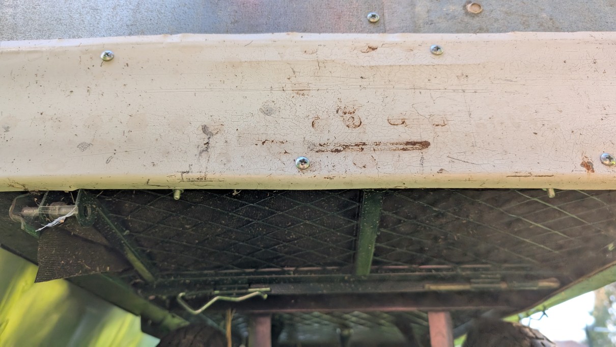 Figure 5. Metal trim (repurposed material) extends from underside of cart to above the bottom edge of the side wall panel exterior. Angled edge of the trim extends under the cart edge to hold it in place. Lower sheet metal screws on the trim extend into the metal cart edge; upper screws attach to the outer cladding of the side wall.
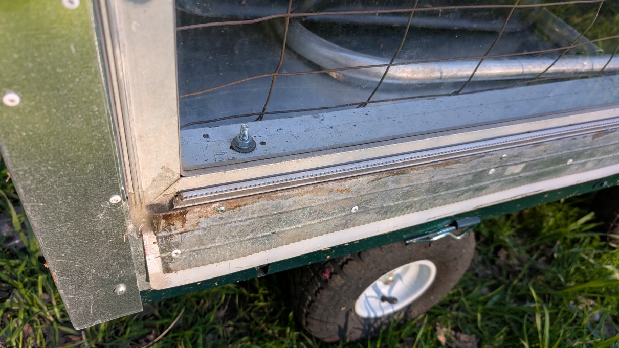 Figure 6. Front window base is anchored and sealed by a metal channel bolted through floor on the inside and several joined pieces of metal trim that hold down the aluminum window frame. Weatherstripping and silicone caulk were used to seal seams.
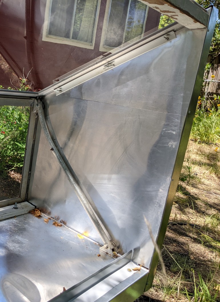 Figure 7. Aluminum angles on side walls support the sides of the top window. They are attached with machine screws that extend through the panel. Part of wood piece that supports the top edge of the window is visible at top right.
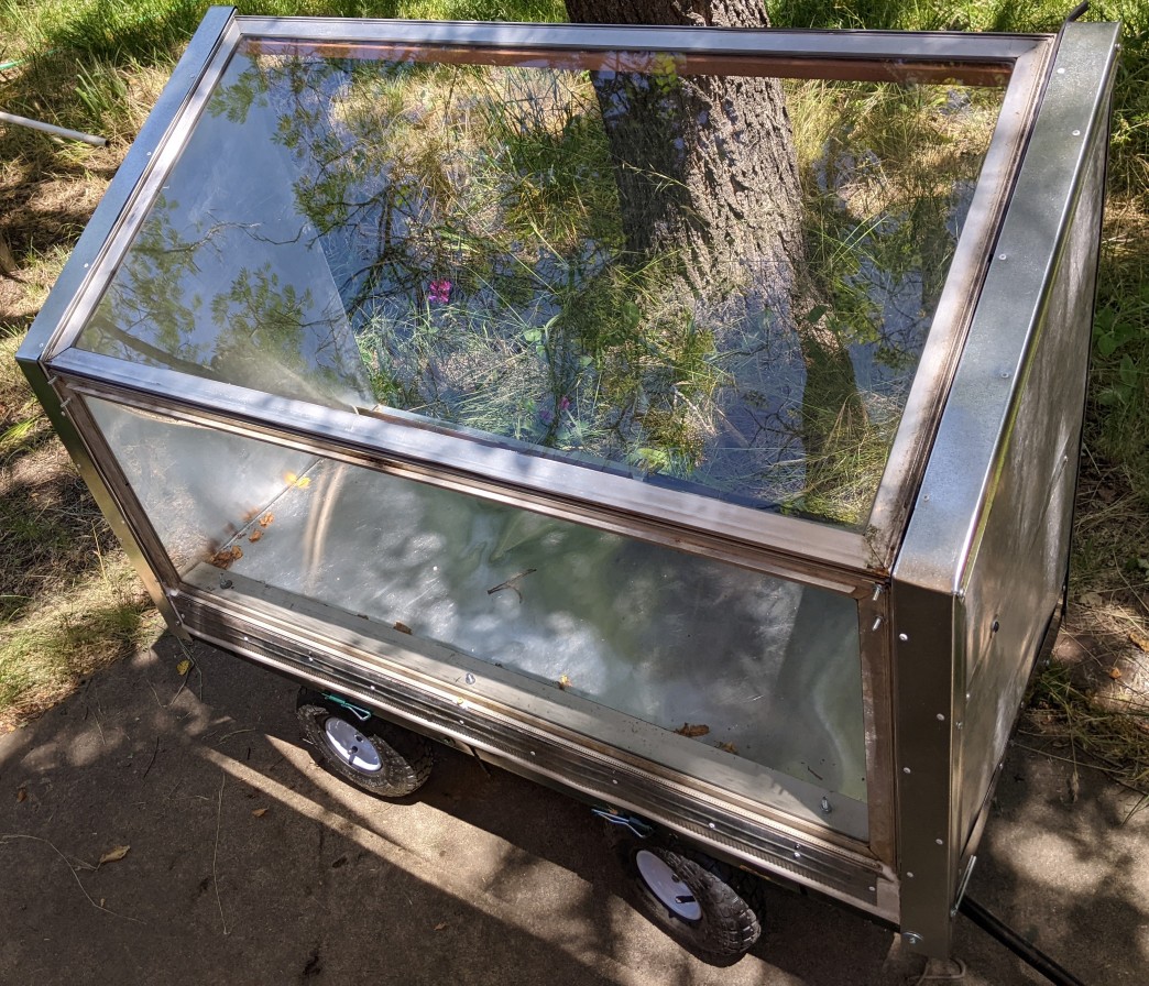 Figure 8. Top window mounted before additional metal brackets were attached at lower corners. A protruding angle from the top widow frame fits into a groove on the top edge of the front window frame to provide a stable joint. Sides of the top window are supported as shown in Figure 7. A wood piece attached to both side walls stabilizes the top of the window and is used to secure the back door framing. The wood piece was later covered with metal angle and flashing.
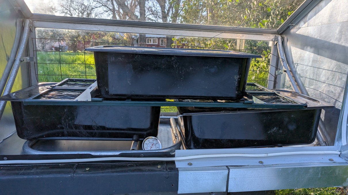 Figure 9. Metal angles with weatherstrip gasket are mounted to the floor to form a surface for sealing the back door panel. The line of these angles continues up the side wall (right) and the top edge (Figure 10). On the bottom, a black metal piece (left) had two angles that make up the seal and cover the bottom panel. On the left side, two pieces of L angle flashing are used to do this.
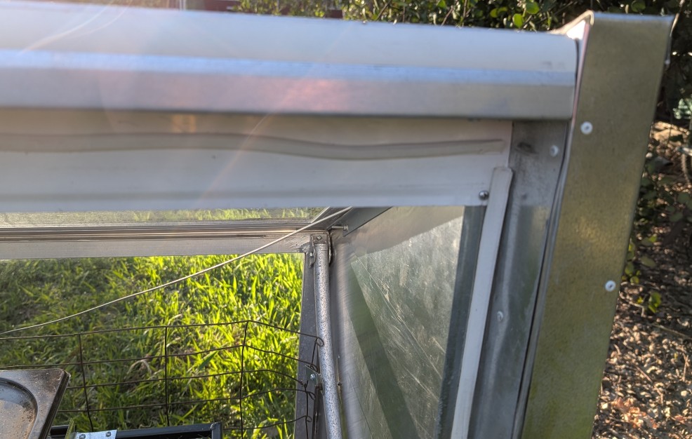 Figure 10. Continuation of rear door seal showing the upper right corner where the side wall angle aligns with the top angle. Note that top wood piece is covered with flashing.
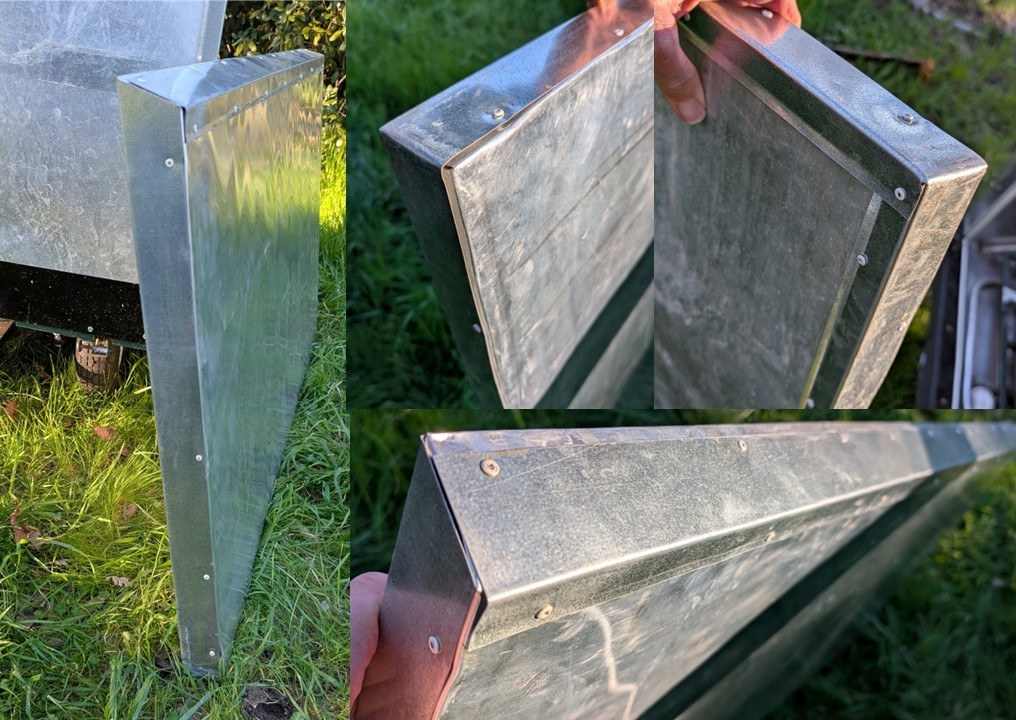 Figure 11. Removable rear wall of solar oven. Both sides are cal with aluminum flashing and edges are capped with drip edge flashing. On the slanted top edge (left and bottom), the short drip edge angle is oriented to the inside of the oven. On the sides and bottom edges (center and upper right) the short drip edge angle is to the outside of the wall.
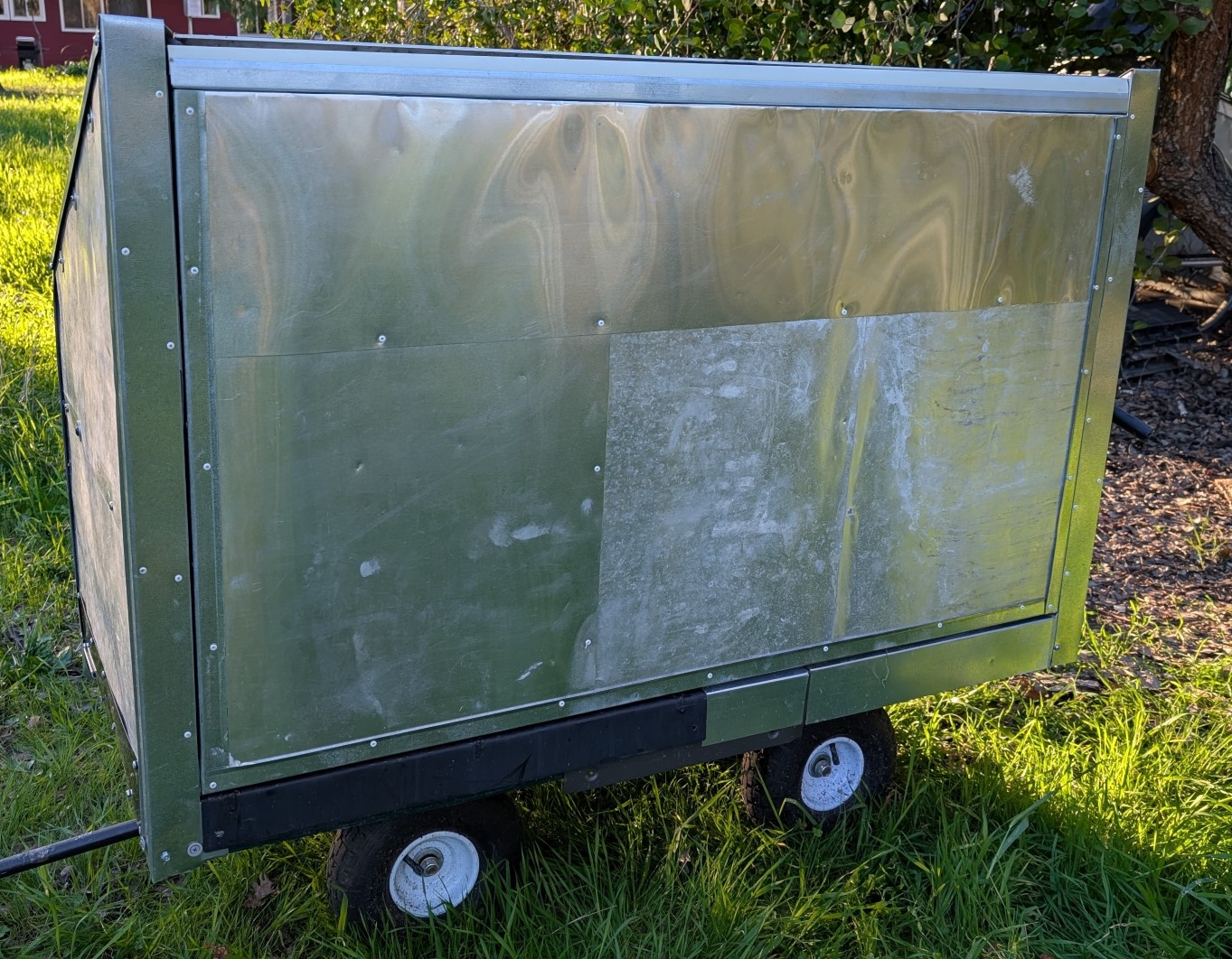 Figure 12. Removable rear wall of solar oven in place on back of oven. Note that 3 pieces of flashing were overlapped to clad the outside rear wall, with rivets used to reinforce the seams.
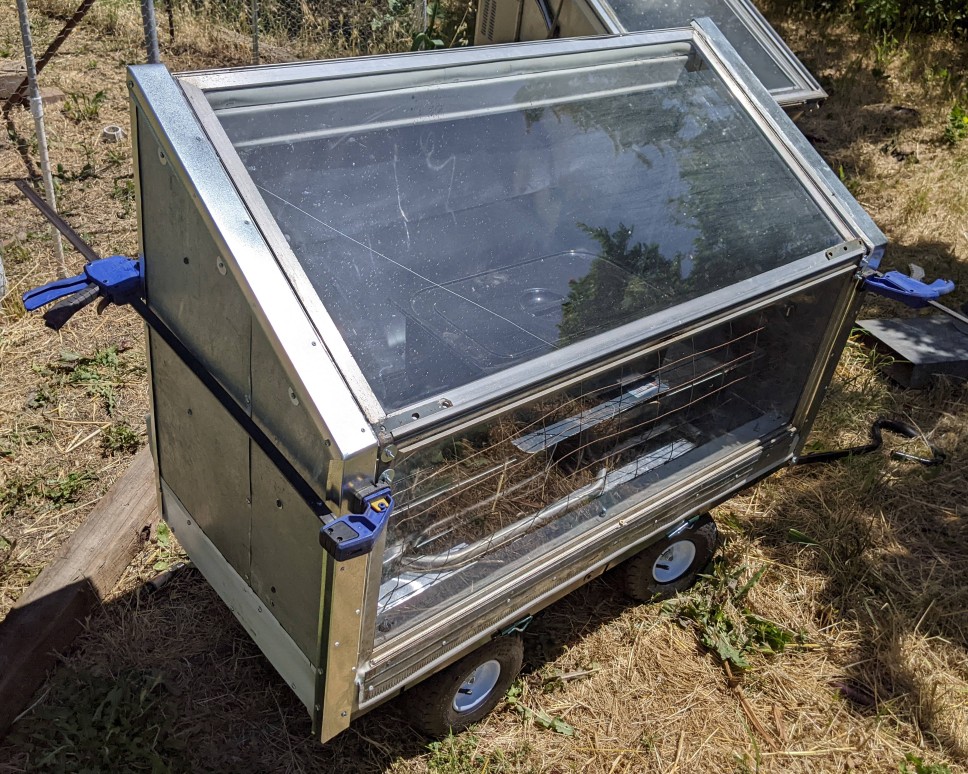 Figure 13. Completed solar oven with bar clamps being used temporarily to hold back panel in place. Note black steam table pans used for soil or media and wire mesh to keep these from sliding into the front window when the oven is moved.
We are using stainless steel steam table pans with lids (about 21" L x 13" W x 6 " D") to hold media or soil that is being heated (Figures 1, 9, 13). The pans are coated with heat-resistant black spray paint to absorb IR and facilitate heating. Air is allowed to circulate around each of the pans. Repurposed aluminum tubing pieces provide air space under the pans and the removable sides from the cart were joined and used to make a separator between upper and lower layers of the pans. We have only used 3 pans, but at least 4 would fit. To prevent the pans from sliding into the front window with the cart is moved, a piece of 2 x 4 inch wire fence fabric was mounted in front of the window (Figures 1, 9, 13).
Changelog: 2/16/2025 original version posted
return to Phytosphere gear page