Irrigation wand and flow control for bench leachate testing
Version 3/19/2021
We have worked with several types of irrigation wands when running bench leachate tests and have had difficulty finding an off-the-shelf wand that works well for the range of containers sizes used in restoration nurseries. In particular, small, closely spaced containers are challenging to irrigate quickly and precisely. The wand in Figure 1 represents the most versatile and easy-to-use wand we have come up with. All the parts are easily available online or at hardware stores and the pieces can be put together in a few minutes. Using the wand with the appropriate tip provides a low pressure stream of water that can be directed into even small containers.
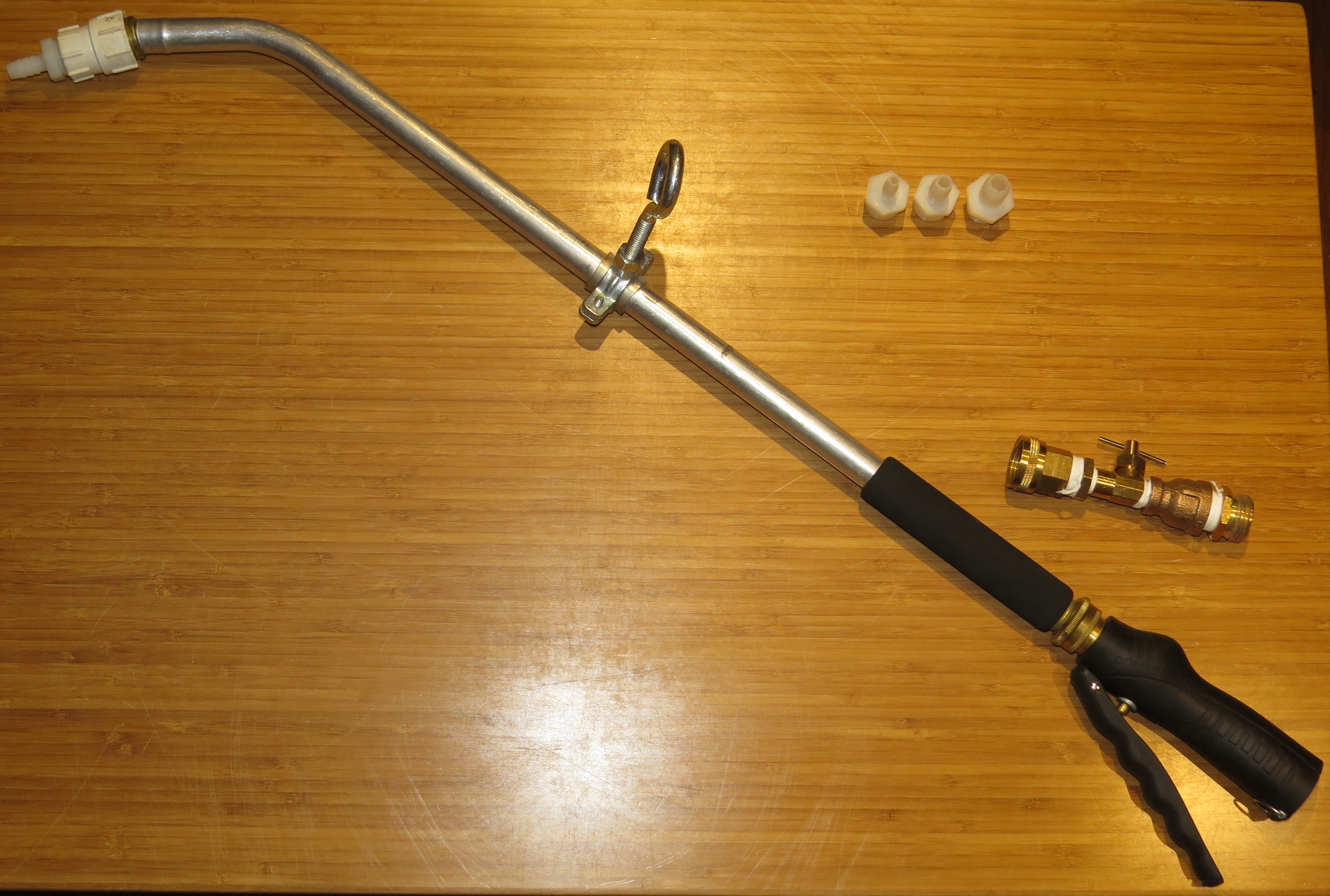 Figure 1. Irrigation wand for bench leachate testing showing full wand with attached hanger, tips of three diameters, and a needle valve flow control, which is attached between the wand and the hose.
To accurately deliver the same volume of water to each container in a test array, the flow rate needs to be constant and calibrated to a rate that is appropriate to container size, head space, and drainage rate. Although a ball valve hose shutoff can be used to control flow, these are very difficult to adjust accurately, especially at low flow rates. On this page, we describe how to assemble a needle valve flow control (for flow rates up to about 125 ml/s) and a gate valve flow control (for higher flow rates) that are much easier to adjust precisely.
In some nurseries, water pressure is variable due to uneven source pressure or changes in pressure due to other irrigations starting or stopping. To maintain the calibrated delivery rate during a bench leachate test, it may be necessary to frequently check and readjust the irrigation flow rate. One advantage of this irrigation wand is that if the stream is directed upward, the height of the water column can be used to quickly judge if the flow is still in an acceptable range and to readjust the flow as needed (Figure 2). Furthermore, if it is possible to irrigate the containers with the tip pointed at an upward angle as shown in Figure 3, changes in flow related to uneven line pressure can be detected and corrected on the fly with a little practice.
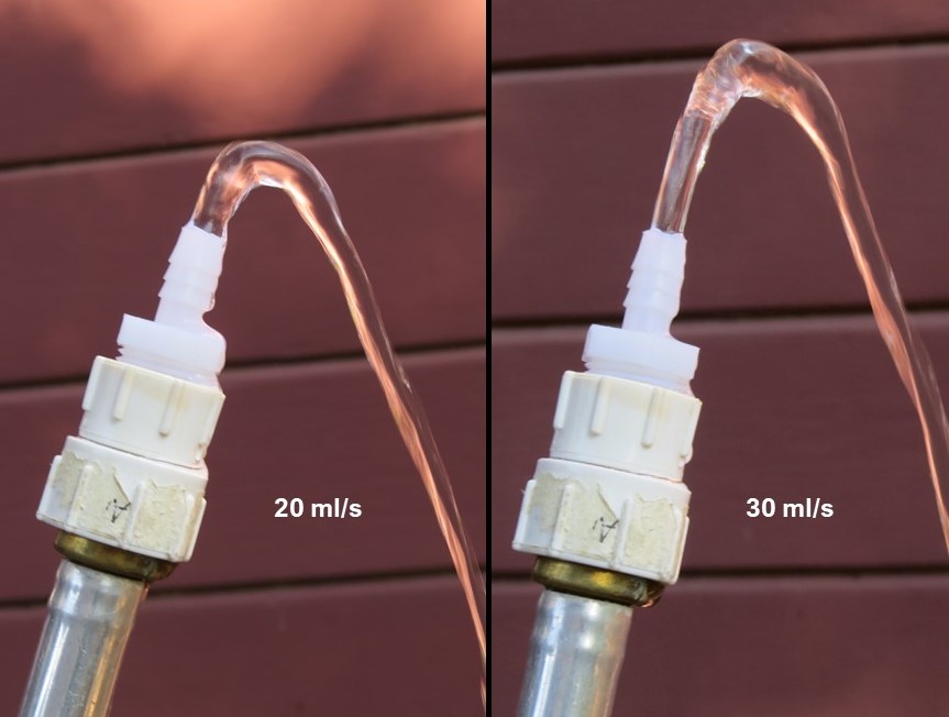 Figure 2. With the tip of the irrigation wand pointed upward, differences in flow rate can be seen by observing the height of the water stream. This image shows the water stream from the 0.375 inch (9.525 mm) hose barb (ID of barb is 0.25 inch/6.35 mm) at flow rates of 20 ml/s (left) and 30 ml/s (right).
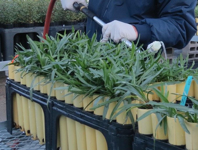 Figure 3. If water pressure fluctuates, the flow rate needs to be checked frequently to ensure that the calibrated flow rate is maintained. If irrigation is conducted with the irrigation wand pointed upward, the arc of the water stream can be observed for changes that correspond to differences in flow rate. This image shows plants in LT8/SC10 containers being irrigated with the 0.25 inch (6.35 mm) barb tip (ID of barb is 0.125 inch/3.18 mm) at a flow rate of 10 ml/s.
Abbreviations
Note - these are standard abbreviations used in product descriptions for the items described below. Parts are numbered sequentially.
- ID = inner diameter
- HT = hose thread
- PT = pipe thread
- HB = hose barb
- M = male (external threads)
- F = female (internal threads)
Irrigation wand
- 1. Dramm Handi-Reach handle - 24 inch (61 cm) (Figure 1). This is the long portion of the wand. It has a 45-degree bend near the end and hose connections at either end (0.75 inch [1.9 cm] MHT and FHT).
- 2. Dramm Touch N' Flow Pro trigger valve (Figure 4). A hand-activated trigger valve is better for the repeated starting and stopping of the irrigation than valves with thumb controls. This has 0.75 inch (1.9 cm) MHT and FHT connections at the ends.
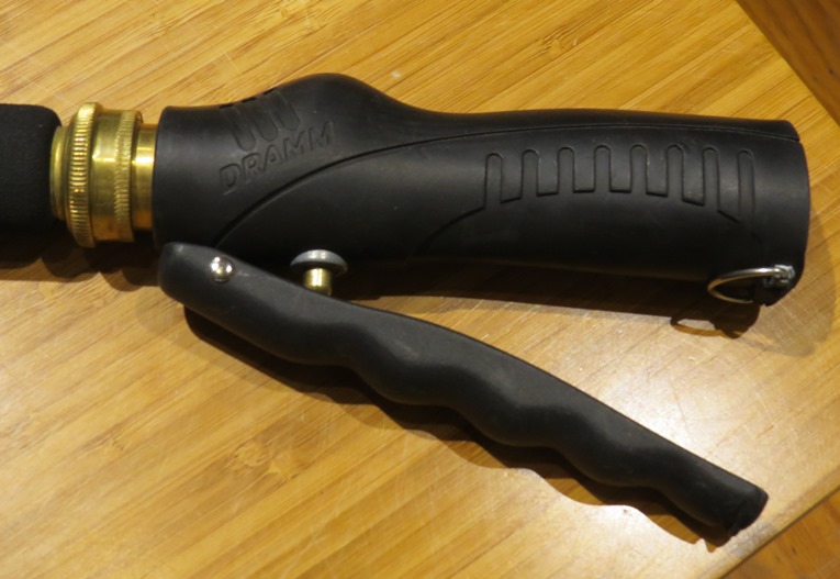 Figure 4. Dramm Touch N' Flow Pro trigger valve. The wand is attached to the MHT fitting to the left. The flow control would be attached to the FHT fitting on the right.
Wand tips for low flow rates
For smaller containers requiring low flow rates (up to about 125 ml/s), we use a tip consisting of a FHT to FPT coupling with a MPT to HB adapter as the tip.
- 3. Coupling - 0.75 inch (1.9.cm) FHT to 0.5 inch (1.27 cm) FPT (Figure 5). This attaches at end of the wand and connects to barb connectors. These couplings are available in brass or plastic.
- 4. Nylon Adapter - 0.5 inch (1.27 cm) MPT x HB (Figure 5). We have used the sizes shown in Table 1 below, but other sizes are available. These fittings are also be available in polypropylene or brass. Note that the hose barb diameter listed for these items corresponds to the ID of the hose that they are made to fit, not the actual ID of the barb itself.
Table 1. Optimal flow rate ranges and corresponding suitable container sizes for hose barb irrigation wand tips.
| Hose barb adapter size | Optimal flow rate range* | Typical container sizes |
|---|---|---|
| 0.25 inch (6.35 mm) HB x 0.5 inch (12.7 mm) MPT | Up to 15 to 20 ml/s | LT6, SC7, RP, LT8/SC10, DP16 |
| 0.375 inch (9.525 mm) HB x 0.5 inch (12.7 mm) MPT | About 20 to 50 ml/s | DP16, TB2/AB35, DP40, DP60 |
| 0.5 inch (12.7 mm) HB x 0.5 inch (12.7 mm) MPT | About 50 to 125 ml/s | DP60, TB46/AB46, TP414/TP4, #1 |
* Optimal flow rate ranges produce a stream of water that can easily be directed into a container but does not generate excessive splash or scour the potting media in the container. Ranges are approximate and will vary based on the characteristics of the container plants being irrigated.
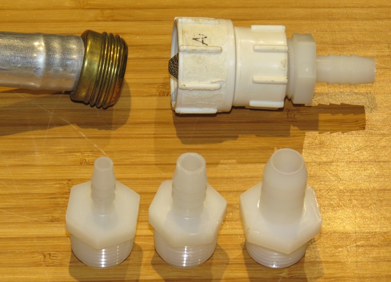 Figure 5. A PVC 0.75 inch (1.9.cm) FHT to 0.5 inch (1.27 cm) FPT coupling with an attached hose barb adapter (upper right) is shown next to the MHT end of the Dramm Handi-Reach handle (wand). Three nylon HB to MPT adapters are shown at the bottom (left to right - 0.25, 0.375, 0.5 inch [6.35, 9.525, 12.7 mm] HB).
Wand tips for high flow rates
For larger containers (TP414, #1, #5) using flow rates from about 100 to 200 ml/s, a larger tip diameter is needed.
- 5. Polyethylene cut off riser - 0.5 inch (12.7 mm) MPT/MPT (Figure 6). This can be threaded into the FPT end of the coupling in place of a hose barb adapter. Other alternatives include a short, threaded 0.5 inch PVC nipple or a 0.625 inch HB (or larger) x 0.5 inch MPT fitting.
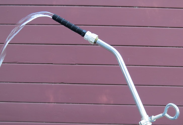 Figure 6. A low energy stream of water for high flow rates (about 100-200 ml/s) can be generated using a 0.5 inch (12.7 mm) cut off riser at the tip of the wand.
High flow rates (200 ml/s or more) may be used for large containers (#5 or larger) to minimize irrigation time. At these flow rates, a single stream of water will typically be too energetic and using a water breaker nozzle helps minimize splash and scouring of the potting media.
- 6. Water breaker nozzle - FHT (Figure 7). This is threaded directly to the MHT fitting at the end of the wand.
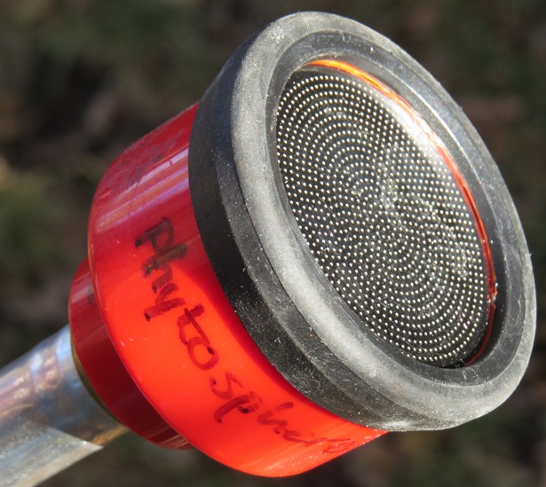 Figure 7. For the highest flow rates (200 ml/s or more) used on large containers, a water breaker nozzle can be threaded on the end of the wand (Dramm Redhead Water Breaker shown).
Hanging bracket
Adding this bracket to the wand facilitates hanging of the wand on a variety of hose wand hangers, fencing, etc.
- 7. Split ring pipe hanger (Figure 8). 1 inch (2.54 cm) ID galvanized split ring hanger.
- 8. Piece of hose, tubing, or other flexible plastic or rubber about 1 inch (2.3 cm) wide, 2.25 inch (5.7 cm) long and 0.125 inch (3 mm) thick.
- 9. Zinc-plated steel plain eye bolt - 4 inch (10 cm) long The split ring hanger shown in Figure 8 can be attached to a 3/8 inch thread diameter, 16 threads per inch (TPI) bolt. Using an eye bolt provides more options for hanging than does a straight bolt. The nut that comes with the eye bolt can be tightened down to the hanger after the eyebolt is threaded in to prevent loosening (Figure 8).
Assembly note: The barrel of this wand is smaller in diameter than the inside of a 1 inch ID split ring hanger, so a short piece of flexible plastic or rubber is wrapped around the wand under the ring to obtain a tight fit (Figure 8). We used a slit length of clear plastic tubing (0.5 inch [1.27 cm] ID, 0.113 inch [2.9 mm] wall thickness) that was slit lengthwise. This flexible wrapping also reduces the chance of bending or puncturing the thin aluminum tubing of the wand when the steel bracket is tightened.
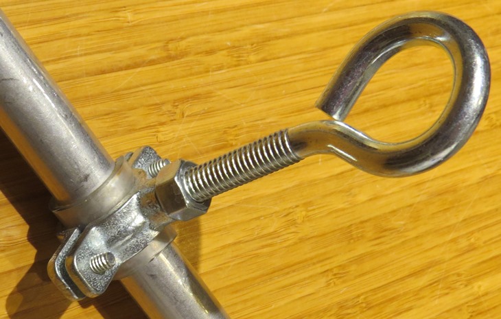
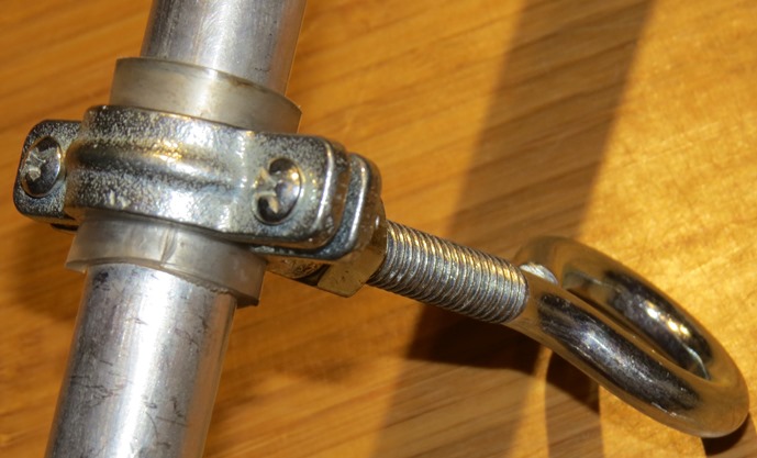 Figure 8. Two views of the hanging bracket attached to the wand. Note the slit piece of clear tubing between the pipe hanger and the wand.
Flow control valves
Needle valve flow control
A flow control with a brass needle valve (Figure 9) is placed before the trigger valve to provide precise adjustment of flow, especially at low flow rates. This flow controller works for flow rates up to about 125 ml/s. Use Teflon tape at all joints. Parts are listed below from left to right as seen in Figure 9. PVC versions of many of these fittings may be available, but brass is likely to be more durable.
- 10. Brass coupling - 0.75 inch FHT to 0.25 inch FPT.
- 11. Brass reducing hex nipple - 0.5 inch MPT to 0.25 inch MPT.
- 12. Brass Needle Valve with 0.25 inch MPT and FPT connections. For a needle valve with 0.25 inch MPT connections on both ends, you will need to change the first two fittings listed above. Note that many needle valves come with compression fittings on the ends; these will not adapt to standard pipe thread fittings.
- 13. Brass reducing coupling - 0.5 inch FPT to 0.25 inch FPT.
- 14. Brass adapter - 0.75 inch MHT to 0.5 inch MPT.
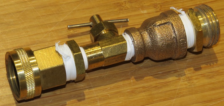
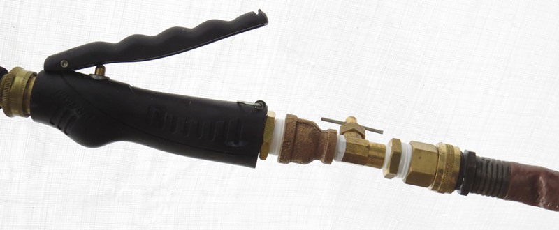 Figure 9. Needle valve flow control for low irrigation flow rates. Connect valve between the hose and the trigger valve of the wand.
Gate valve flow control
This valve is best for relatively high flow rates and is needed for flows beyond the range of the needle valve flow control shown above (more than about 125 ml/s). Although this gate valve flow control can be used at very low flow rates (to 10 ml/s), it is more difficult to adjust precisely at low flow rates than the needle valve.
The gate valve flow control shown in Figure 10 uses a 0.75 inch brass gate valve and PVC couplings, but the unit could be made with all brass fittings or a PVC gate valve can be used. A 0.5 inch gate valve could be used instead of a 0.75 inch valve with the appropriate couplings. Use Teflon tape at all joints. Parts are listed below from left to right as seen in Figure 10.
- 15. Coupling (PVC or brass) - 0.75 inch FHT to 0.75 inch MPT.
- 16. Brass gate valve - 0.75 inch (FPT-FPT)
- 17. Coupling (PVC or brass) - 0.75 inch MHT to 0.75 inch MPT.
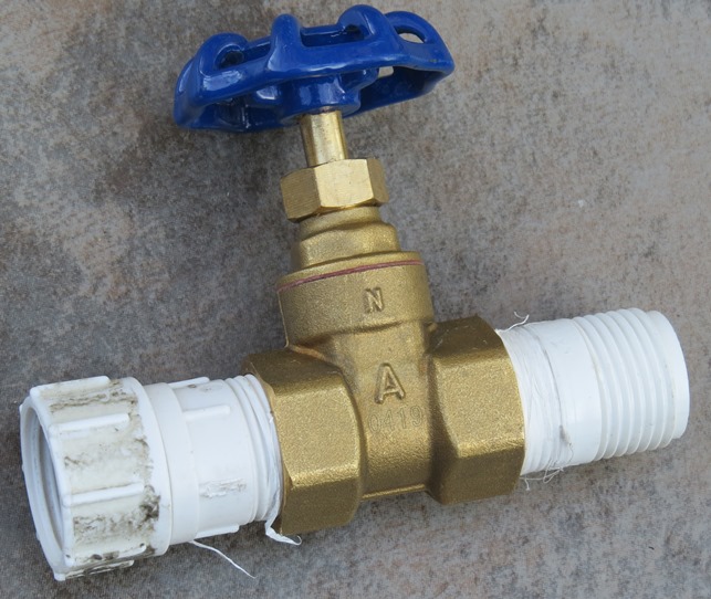 Figure 10. Gate valve flow control for high irrigation flow rates. Connect valve between the hose and the trigger valve of the wand.
Updated 3/19/21: Changed hose barb (HB) size references to match how they are listed in catalogs, etc., that is, by the ID of the hose for which the barb is intended. The sizes listed in the current page version are needed for ordering or selecting parts. For nylon hose barbs, this diameter is about 0.125 inch (3.175 mm) larger than the actual ID of the opening on the hose barb, which was listed in the original version of this page.
return to Phytosphere gear page